3D Scene
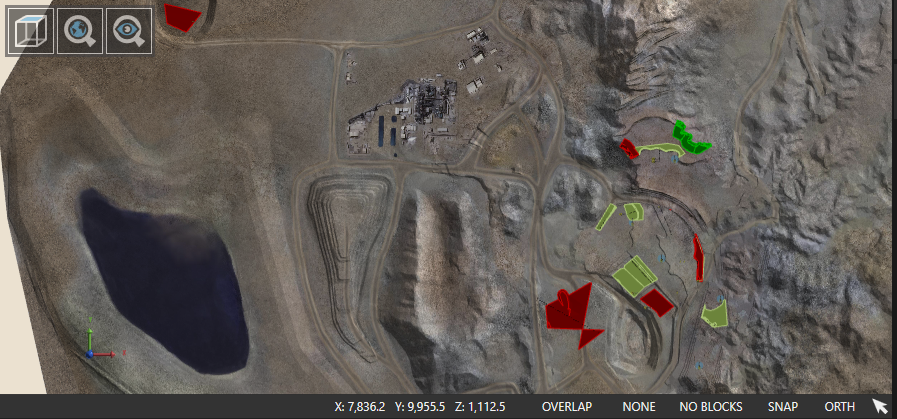
On opening XECUTE, the 3D Scene displays. The Scene is the main screen of XECUTE and displays the 3D view of the mine site topography. The 3D Scene is a visual tool that places the important information required to effectively schedule a mining operation on the one screen.
Site Settings
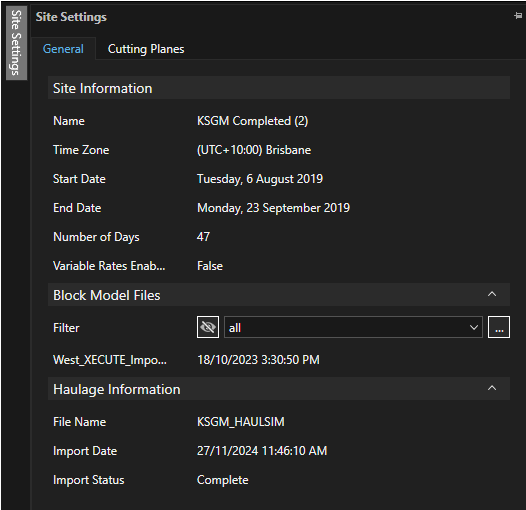
The Site Settings panel has tabs for general site information and configuration of cutting planes in the 3D Scene.
General info
Read only site data (set in XECUTE Config).
Block Model Files
Lists the imported block models for the site.
The filter dropdown lists configured block model filters.
Haulage Information
Read-only data about the imported Haulage model (if imported)
Scene Manager
The Scene Manager is a panel in the main window that controls the visibility of all items in the scene. The visibility of scene items can be set here or in their respective menu tab (toolbar at base of XECUTE Client application).
Select the item in the scene manager to have it display in the 3D Scene.
Navigation
Navigate the 3D Scene using your mouse. The following controls are used.
-
Left-click and drag pans the mine map around the screen.
-
Right-click and drag rotates the mine map.
-
Mouse wheel zooms in and out of the mine map.
-
Ctrl+Right-click centres the Scene on point under mouse.
3D Scene floating toolbars.
|
Item |
Field |
Description |
|---|---|---|
|
|
Top Down Camera |
The angle of the camera is placed from above, providing a top-down view of the mine site. |
|
|
Zoom World |
Zooms to the extents of all graphic objects (topography included). |
|
|
Zoom Objects |
Zooms the view so that all activity areas and resources are visible in the viewer. There is no rotation of the camera angle. |
|
|
Markup |
Toggle the markup icons, Click an icon to create Note, Arrow or Polyline markups.
|


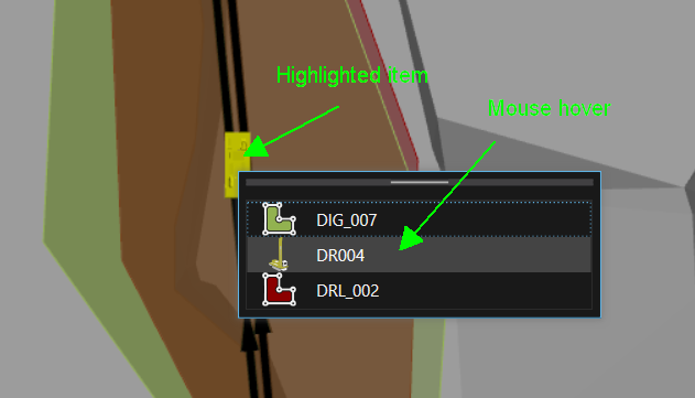
Selection of scene items
By default, the object directly under the cursor is selected when you click in the scene. If there are stacked items use the Selection Helper (Shift-click) to choose an item to select. As you hover over the item in the list, the item is highlighted in yellow in the scene.
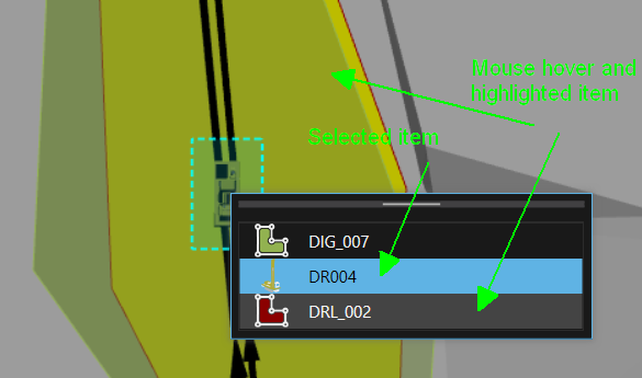
If an item is already selected in the scene when shift-click is used the selected item is shown in the helper as a blue row and the mouse hover item is grey in the helper and yellow in the scene.
Scene toolbar
|
Item |
Field (Shortcut key) |
Description |
|---|---|---|
|
|
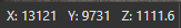
Cursor Position (Status Bar) |
The X,Y,Z coordinates of the cursor. |
|
|
Overlap Mode |
Sets how overlaps between activity areas are treated. Toggle to cycle through the overlap modes.
|
|
|
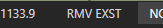
Input Restriction |
Limits the cursor movement when drawing an activity area. Click to open a pop-up window and set the restriction type and value. Displayed values:
|
|
|
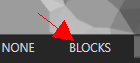
Activity Area - Block Rending Mode |
Cycle through the options:
|
|
|
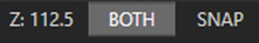
Cursor Snapping |
Click to toggle snapping when editing an activity area (if grey background, snapping is disabled). |
|
|
ORTH/PERS (O Key - orthographic) (P Key - perspective) |
Click to toggle between Orthographic and Perspective projection types. |
|
|
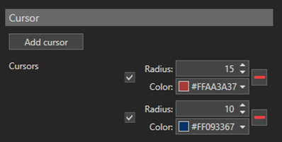
Cursor Type |
Toggles the bullseye cursor on and off. The cursor type is defined in the Graphics Setting control as shown below (click the Cog icon in the title bar next to the Help icon).
|
|
|
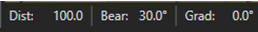
Active line segment (Status Bar left side) |
Displays when vertices are moved. Displays the bearing, distance and gradient from the nearest vertex (black) to the currently selected vertex (orange).
|